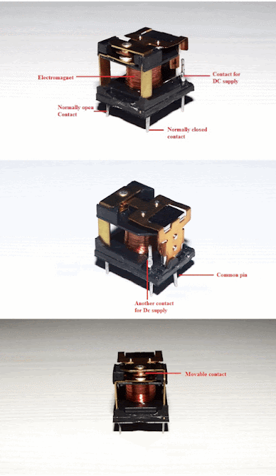
We use relays for a wide range of applications such as home automation, cars and bikes (automobiles), industrial applications, DIY Projects, test and measurement equipment, and many more. But what is Relay? How a Relay Works? What are the Applications of Relays? Let us explore more about relays in this guide.
What is a Relay?
A Relay is a simple electromechanical switch. While we use normal switches to close or open a circuit manually, a Relay is also a switch that connects or disconnects two circuits. But instead of a manual operation, a relay uses an electrical signal to control an electromagnet, which in turn connects or disconnects another circuit.
- Electromagnet
- Mechanically movable contact
- Switching points and
- Spring
Generally two more contacts will be present, called as switching points to connect high ampere load. Another contact called common contact is present in order to connect the switching points.
These contacts are named as normally open (NO),normally closed(NC) and common(COM) contacts.
We can use a Relay either in a AC circuit or a DC Circuit. In case of AC relays, for every current zero position, the relay coil gets demagnetized and hence there would be a chance of continues breaking of the circuit.
So, AC relays are constructed with special mechanism such that continuous magnetism is provided in order to avoid above problem. Such mechanisms include electronic circuit arrangement or shaded coil mechanism.
How a Relay Works?
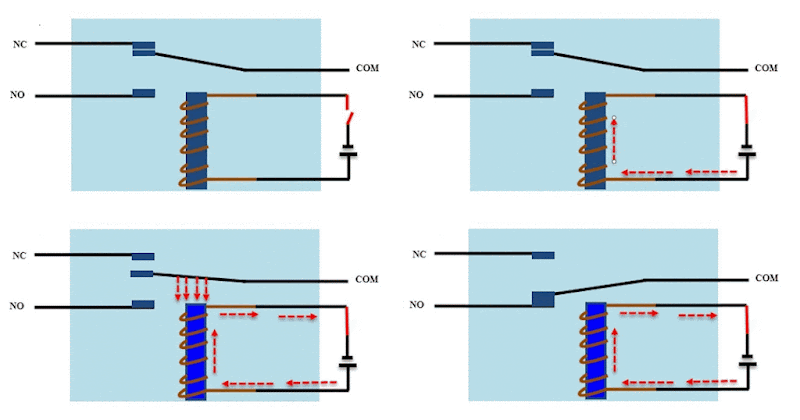
The following animation shows a simplified working of a relay.
- Relay works on the principle of electromagnetic induction.
- When the electromagnet is applied with some current, it induces a magnetic field around it.
- Above image shows working of the relay. A switch is used to apply DC current to the load.
- In the relay, Copper coil and the iron core acts as electromagnet.
- When the coil is applied with DC current, it starts attracting the contact as shown. This is called energizing of relay.
- When the supply is removed it retrieves back to the original position. This is called De energizing of relay.
- There are also such relays, whose contacts are initially closed and opened when there is supply i.e. exactly to opposite to the above shown relay.
Solid state relays will have sensing element to sense the input voltage and switches the output using opto-coupling.
Relay Contact Types
As we have seen that relay is a switch. The terminology “Poles and throws” is also applicable for relay. Depending on the number of contacts and number of circuits it switches relays can be classified.
Before we know about this classification of contacts we have to know the poles and throws of a relay switch.
Poles and Throws
Relays can switch one or more circuits. Each switch in relay is referred as pole. Number of circuits a relay connects is indicated by throws.
Depending on the poles and throws, relays are classified into
- Single Pole Single Throw
- Single Pole Double Throw
- Double Pole Single Throw
- Double Pole Double Throw
- Single Pole Single Throw
A single pole single throw relay can control one circuit and can be connected to one output. It is used for the applications which require only ON or OFF state.
Single Pole Double Throw
A single pole double throw relay connects one input circuit to one of the two outputs. This relay is also called as changeover relay.
Though the SPDT has two output positions, it may consist of more than two throws depends on the configuration and requirement of the application.
Double pole single throw
A double pole single throw relay has two poles and single throw and it can be used to connect two terminals of a single circuit at a time. For example, this relay is used for connecting both phase and neutral terminals to the load at a time.
Double pole double throw
A DPDT (double pole double throw) relay has two poles and two throws for each pole. In motor direction control, these are used for phase or polarity reversal.
The switching action between contacts for all these relays is performed when the coil get energized.
Types of Relays
Relays can be classified into different types depending on their functionality, structure, application etc. We listed out some of the common types of relays here.
- goog_893638276Electromagnetic
- Latching
- Electronic
- Non-Latching
- Reed
- High-Voltage
- Small Signal
- Time Delay
- Multi-Dimensional
- Thermal
- Differential
- Distance
- Automotive
- Frequency
- Polarized
- Rotary
- Sequence
- Moving Coil
- Buchholz
- Safety
- Supervision
- Ground Fault
We made a dedicated guide on different types of relays. To learn more about different types of relays, read Classification of Relays.
Relay Applications
Relays are used to protect the electrical system and to minimize the damage to the equipment connected in the system due to over currents/voltages. The relay is used for the purpose of protection of the equipment connected with it.
These are used to control the high voltage circuit with low voltage signal in applications audio amplifiers and some types of modems.
These are used to control a high current circuit by a low current signal in the applications like starter solenoid in automobile. These can detect and isolate the faults that occurred in power transmission and distribution system. Typical application areas of the relays include
- Lighting control systems
- Telecommunication
- Industrial process controllers
- Traffic control
- Motor drives control
- Protection systems of electrical power system
- Computer interfaces
- Automotive
- Home appliances
How to Test a Relay?
Since they are electromechanical devices, relays can wear out eventually and stop working over time. But there are few techniques to test if a relay is working or not. These techniques include:
- Testing a Relay with a Multimeter
- Build a simple circuit to test the Relay
- Use a DC Power Supply to see whether a relay is functioning properly
To learn more about testing a relay, read How to Test a Relay with Multimeter.
Conclusion
A simple introductory guide on Relays. We learned What is Relay and how it works by taking a look at the internals of a typical electromechanical relay. We also listed out some of the different types of relays and also few applications of relays. Finally, we saw different ways to test a relay.


This post is so useful and valuable to increase our knowledge Enclosure accessories I am happy that you have shared great info with us. Grateful to you for sharing an video like this.
ReplyDelete