What is a Ladder Diagram?
A Ladder Diagram is one of the simplest methods used to program a PLC.
It is a graphical programming language that evolved from electrical relay circuits.
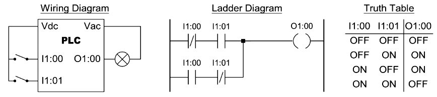
Each program statement is represented with a line, called the rung, that has all relevant inputs to the left and the output to the right.
The output device of a rung is energized if electric power can conceptually flow from the left side of the rung to the right side. Input devices are assumed to block the flow of power if they are not activated.
During the execution of a ladder diagram, the PLC reads the states of all inputs, then determines the states of all outputs starting from the rung at the top side, going down to the last rung, and finally updates the state of the output devices.
Naming Convention
During the development of a PLC program, we must use specific names to identify the inputs, outputs, memory flags, timers, and counters.
PLC manufacturers use a variety of approaches in naming the inputs, outputs and other resources.
A typical naming convention is to identify inputs with the letter “I” and outputs with the letter “O”, followed by a 1-digit number that identifies the slot number and a 2-digit number that identifies the position of the input or output in the slot.
For example:
I1:00 refers to the first input of slot 1
O2:00 refers to the first output of slot 2.
Some manufactures number the inputs or outputs starting from 00, while others use the number 01 to identify the first input or output. It is also common to use numbers like 400 e.t.c.
The state of output can be also used as an input in a ladder diagram. In such a case the PLC uses the state of the specific output device that is stored in the output image memory.
Relay Logic Instructions
Examine if Closed (XIC)
If the input device is ON or Closed, then the corresponding bit in the data memory (input image) is set to true, thus allowing (conceptually) the energy to flow from its left side to its right-hand side.
Otherwise, it is set to false, thus blocking the energy.
Examine if Open (XIO)
If the input device is OFF or Open, then the corresponding bit in the data memory (input image) is set to true, thus allowing (conceptually) the energy to flow from its left side to its right-hand side.
Otherwise, it is set to false, thus blocking the energy.
Input Transition Sensing Instructions
Positive Transition Sense (PTS)
The condition of the right link is ON for one ladder rung evaluation when a change from OFF to ON at the specified input is sensed.
Negative Transition Sense (NTS)
The condition of the right link is ON for one ladder rung evaluation when a change from ON to OFF at the specified input is sensed.
Output Instructions
Output Energize (OTE)
If the condition of the left link of the OTE is ON then the corresponding bit in the output data memory is set. The device wired to this output is also energized.
Negative Output Energize (NOE)
If the condition of the left link of the OTE is OFF then the corresponding bit in the output data memory is set. The device wired to this output is also energized.
Output Latch/Set and Output Unlatch/Reset (OTL), (OTU)
If the condition of the left link of the OTL is momentary ON then the corresponding bit in the output data memory is set, and remains set even if the condition switches to the OFF state. The output will remain set until the condition of the left link of the OTU is momentary ON.
Basic Logic Functions
Two Input OR Function
The output is ON if any of the two inputs is ON.
Two Input AND Function
The output is ON if both of the two inputs are ON.
Two Input NAND Function
The output is ON if any of the two inputs is OFF.
Two Input NOR Function
The output is ON if both of the two inputs are either OFF or ON.
Set/Reset Latch Instructions
Set/Reset Latch using a Hold-in contact
Set/Reset Latch using Latch/Unlatch outputs
Notes:
O1:00’ means that the output is unchanged
If both inputs are ON then normally the output is OFF, since the Unlatch rung appears last in the ladder diagram.
Timer Instructions
Timer Instructions are output instructions used to time intervals for which their rung conditions are true (TON), or false (TOF).
These are software timers. Their resolution and accuracy depend on a tick timer maintained by the microprocessor.


Comments
Post a Comment