
Ladder Logic for Flow Meter Totalizer

 This is a PLC Ladder Logic to calculate the flow rate and also count the total flow or totalizer.

Flow Meter Totalizer


By using some math, bit and comparator functions, prepare a PLC program that can calculate the flow rate of gas and also count the total flow.


Problem Solution:

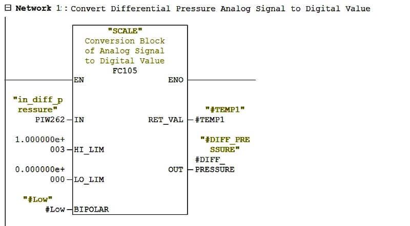
To calculate flow, first we have to measure differential pressure.

To measure differential pressure, Differential Pressure transmitter installed at pipe line.

Range of DP transmitter is 0-1000 Pa.

Output of this transmitter is in standard electrical signal which is 4-20 mA. Convert this signal into digital signal by connecting transmitter to AI module of PLC.

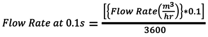
To find the Flow Rate, Apply formula ( Flow Rate = k √∆P ) given by the designer using math block in PLC.

Prepare a logic for Flow totalizer using math function in PLC.

NOTE :

In this example, we are assuming the transmitter output 4-20 mA is equivalent to “Differential Pressure” instead of direct flow reading. So we are applying the square root function in PLC to derive the equivalent flow rate from this measured “differential pressure”.


PLC Address & Data Types


PLC Ladder Logic

Network 1 :


In this Network 1, we are converting Analog Signal of the Differential Pressure Transmitter which is in 4 – 20 mA to digital value 0-1000 Pa.

Network 2 :
In the Network 2, We are finding Flow Rate by applying formula( Flow Rate = k √∆P ). Where k is the constant which is 10000 in my case and ∆P is the differential pressure in Pascal, which we are getting from the above network.

So we are using square root block and multiplication block to achieve this formula.

The unit of flow rate is m3/hr.

Network 3 :
Now this is tricky network, if you count the total flow then you must do increment the flow rate at every minimum time frame whichever is possible.

So here I have used clock memory here and minimum possibility of time frame of my PLC is 0.1s (seconds). So I have to find out the flow rate at 0.1s for that.

I have used the below formula to find out the flow rate at 0.1s

Network 4 :

In this Network 4, we are doing addition of flow rate at 0.1s at every 0.1s and save it to Total_Flow.

-END-

Comments

Popular posts from this blog

Ferrules and Cross Ferruling

 Ferrules are identification labels provided for every wire terminations in an instrument, equipment, or electrical/instrumentation control panels. These tube-shaped sleeves can be inserted easily on each individual wire in a multi-core cable. In earlier days fixed digits/letters are used as ferrules, but now Instrumentation engineers/technicians prints out desired ferrules by using a ferrule printing machine. Typical Ferrule The numbers/ letters on the ferrules will be given as per the approved electrical hook up or loop diagrams. This helps technicians to easily identify a particular loop/wiring from a series of terminal blocks and to troubleshoot the desired terminal connection. Separate numbers on the ferrules distinguish the positive and negative polarities of wires, thus ensure the polarity protection of the instrument. Cross Ferruling  As a wire is connected on its both ends, it is quite useful to use a cross reference method for wire identification. Unlike normal ferru...

What is a Torbar? – Averaging Pitot Tubes

 The Torbar is employed for flow measurement of liquids, gases, or steam in circular, square, or rectangular section ducts for large flow rates. The Torbar is an insertion type multi-port self-averaging primary sensor for flow measurement. Torbar TORBAR is a set of Pitot tubes mounted on a bar across the pipeline with no moving parts. An averaging Pitot tube is a technology, while TORBAR is a manufacturing brand name. There are several brands available in the market with VERABAR, ANNUBAR, etc. Averaging Pitot Tube Principle Purpose Averaging Pitot tube can be employed when the average velocity of the flow profile, rather than the velocity in a specific point in the cross-section is desired. Averaging Pitot Tubes Principle It measures the differential pressure between the static pressure tap and the tap of full pressure of a stream. Thus such magnitude of differential pressure is directly proportional to the square of the flow rate. Working The TORBAR is designed in such a way that ...

Dissolved Oxygen Analyzer Working Principle

 What is dissolved oxygen ? Dissolved oxygen refers to oxygen dissolved in water. Its concentration is expressed as the amount of oxygen per unit volume and the unit is mg/L. Biologically, oxygen is an essential element for respiration of underwater life and also acts as a chemical oxidizer. The solubility of oxygen in water is affected by water temperature, salinity, barometric pressure, etc. and decreases as water temperature rises. Measurement of dissolved oxygen by the membrane electrode method The membrane electrode method measures a diffusion current or reduction current generated by the concentration of dissolved oxygen or partial pressure of oxygen to obtain the concentration of dissolved oxygen. This method is not affected by the pH value of water being measured, oxidation and reduction substances, color, turbidity, etc. and the measurement method offers good reproducibility. When a sensor is inserted into water, an air layer forms on the membrane (Teflon membrane). The ox...