Jump instruction in ladder logic is used to skip some process or rungs according to the requirement. It is paired with Label which is used to limit the skipping the process.

Let’s study the working of jump instruction using an example.
Example – JUMP Instruction in PLC Ladder Logic
There are seven motors used for various processes. On-demand base Motors 4, 5 & 6 are needed.
Design a program to skip motor 4, 5 & 6 when it does require for the process.
PLC Program

Program Description
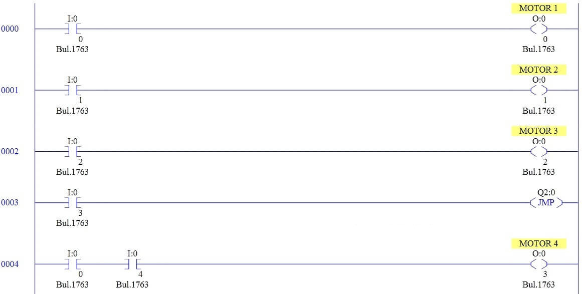
RUNG 0000
The input I:0/0 is used to turn on Motor 1.
RUNG 0001
The input I:0/1 is used to turn on Motor 2.
RUNG 0002
The input I:0/2 is used to turn on Motor 3.
RUNG 0003
The input I:0/3 is used to initiate the jump function (Q2:0).
RUNG 0004
The input I:0/0 & I:0/4 is used to turn on Motor 4.
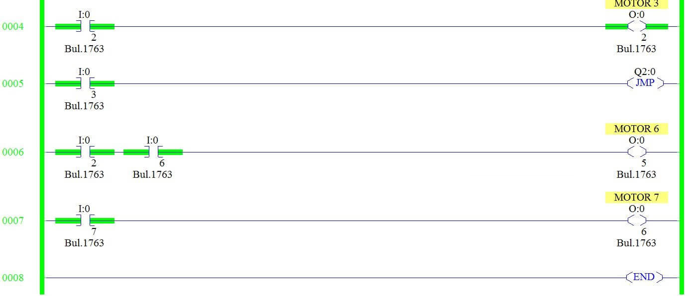
RUNG 0005
The input I:0/1 and I:0/5 is used to turn on Motor 5.
Rung 0007
Label instruction is used to finish the jump function.
The input I:0/6 and I:0/2 is used to turn on Motor 6.
When JUMP condition is OFF :


When Jump condition is not initiated or enabled, all outputs will turn ON/OFF according to respective input.
When JUMP condition is ON :

Rung 4, 5 & 6 are completely skipped till label function.
Jumping Backward
If we use label instruction first and then jump will perform jumping backward function.

Jump instruction resumes program execution before the label and after the jump instruction. In between rungs will work on respective inputs.
Conclusion:
The above-explained jump instruction is for example only. It may vary from real-time applications.
-END-
Comments
Post a Comment