Let’s study the working of SAVE and BR instructions in Siemens PLC programming.
SAVE and BR Instructions in PLC
Block Description
SAVE:
Save coil-like symbol in Siemens PLC is to saving Result of Logical Operation (RLO) into BR Memory.
BR:
BR contact like symbol in Siemens PLC is to retrieve the output to trigger any other output or block. This bit enables your program to interpret the result of a word logic operation as a binary result and to integrate this result in a binary logic string.
Let’s try to understand SAVE and BR instruction in ladder logic and FBD,
Example 1:
Turn ON Q0.0 using I0.0-When I0.0 is turning ON, it will make Q0.0 to go ON.
Function Block Diagram (FBD):
Save instruction is used to store RLO of I0.0 into BR memory bit of the status word.
By using BR contact, Q0.0 is turned ON.
Example 2:
Turn ON Q0.0 using I0.0 and Q0.1 using I0.1- When input I0.0 is turning ON it will make output Q0.0 to go ON and input I0.1 is turning ON it will make output Q0.1 to go ON.
Ladder Logic:
Function Block Diagram (FBD):
First Save instruction in network 1 is used to store RLO of input I0.0 into BR memory bit of the status word. By using BR contact, output Q0.0 is turned ON.
Second Save instruction in network 3 is used to store RLO of input I0.1 into BR memory bit of the status word. By using BR contact, output Q0.1 is turned ON.
Example 3:
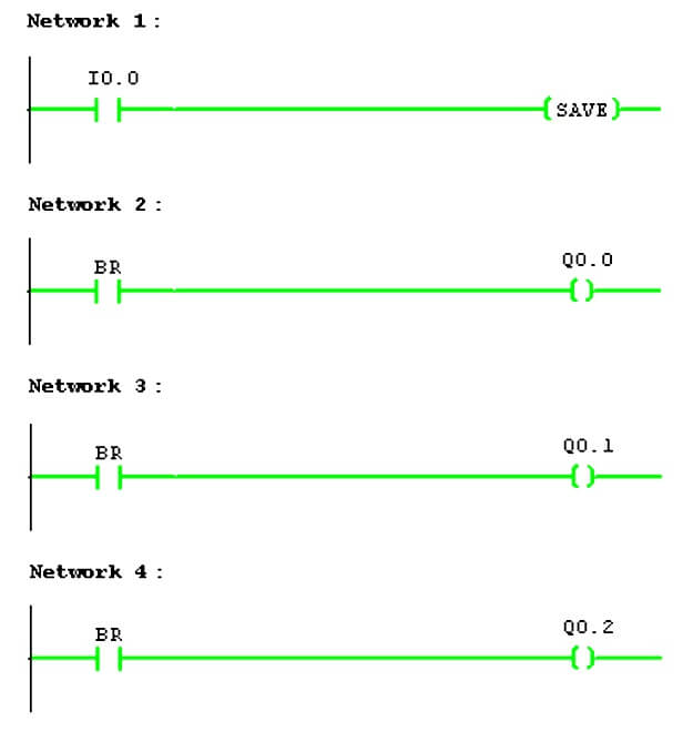
Turn ON Q0.0, Q0.1 and Q0.2 using I0.0 – When input I0.0 is turning ON it will make output Q0.0, Q0.1 and Q0.2 to go ON.
Ladder Logic
Save instruction in network 1 is common for all the BR memory we have used in Networks 2, 3 and 4.
-END-


Comments
Post a Comment