
Pulse Generation using Timer in Siemens PLC

 This article is about a pulse generation PLC program using Siemens TIA PORTAL.

In industries, we use special audio and visual indications to notify the operators about the alarms and trips of the process. Different types of indications are flashing LED, beacons with different tones, etc.

We can set the rate of pulses from slow to fast as per our requirement by changing the timing of the timers. Here we will be discussing the pulse generation using timer instruction in Siemens PLC.

Below I have explained the PLC program for pulse generation.

Inputs and Outputs

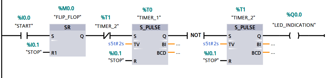
Inputs: START(I0.0), STOP (I0.1)

Outputs: LED_INDICATION (Q0.0)

Timers: T0 & T1

Memory Bit: M0.0

Description
When you press the start button (%I0.0), then the flip-flop (M0.0) energizes then it will pass the signal through NC contact of timer (T2) then timer 1 will energize.
Here I have used S_Pulse timer which will run in our case for 2 seconds after 2 seconds timer will energize.

We can change the timing of the timer to change the flashing rate as per our requirement.

If Timer 1 is not energized then first NOT instruction will energize the Timer 2 allowing output to turn ON for 2 seconds.

Both the timers will run for 2 seconds simultaneously allowing LED to turn ON and OFF for every 2 seconds thus flashing the LED.
-END-


Comments

Popular posts from this blog

PLC Program for Mixing Tank

 Create a ladder diagram for controlling a batch mixing process. Implement a PLC program for mixing tank or Mixing Process using PLC Ladder Logic. PLC Program for Mixing Tank Fig : Mixing tank A tank is used to mix two liquids. The required control circuit operates as follows: A. When the START button is pressed, solenoids A and B energize. This permits the two liquids to begin filling the tank. B. When the tank is filled, the float switch trips. This de-energizes solenoids A and B and starts the motor used to mix the liquids together. C. The motor is permitted to run for 1 minute. After 1 minute has elapsed, the motor turns off and solenoid C energizes to drain the tank. D. When the tank is empty, the float switch de- energizes solenoid C. E. A STOP button can be used to stop the process at any point. F. If the motor becomes overloaded, the action of the entire circuit will stop. G. Once the circuit has been energized, it will continue to operate until it is manually stopped. Solution : A

What is Relay? How it Works? Types, Applications, Testing

 We use relays for a wide range of applications such as home automation, cars and bikes (automobiles), industrial applications, DIY Projects, test and measurement equipment, and many more. But what is Relay? How a Relay Works? What are the Applications of Relays? Let us explore more about relays in this guide. What is a Relay? A Relay is a simple electromechanical switch. While we use normal switches to close or open a circuit manually, a Relay is also a switch that connects or disconnects two circuits. But instead of a manual operation, a relay uses an electrical signal to control an electromagnet, which in turn connects or disconnects another circuit. Relays can be of different types like electromechanical, solid state. Electromechanical relays are frequently used. Let us see the internal parts of this relay before knowing about it working. Although many different types of relay were present, their working is same. Every electromechanical relay consists of an consists of an Electroma

Chlorine dioxide Analyzer Principle

 Chlorine dioxide measurement Chlorine dioxide (ClO2) is an instable, non-storable, toxic gas with a characteristic scent. The molecule consists of one chlorine atom and two oxygen atoms – represented in the chemical formula ClO2. It is very reactive. To avoid the risk of spontaneous explosions of gaseous chlorine dioxide or concentrated solutions, it is generally handled in dilution with low concentrations. ClO2 is soluble in water, but tends to evaporate quickly. Typically it is prepared on site, for example from hydrochloric acid and sodium chlorite. The procedure provides solutions with approx. 2 g/l ClO2 that can be safely handled and stored for several days. Image Credits : krohne Sensor Parts : Reference electrode Applied chlorine dioxide specific potential Current needed to maintain the constant potential Counter electrode Measuring electrode The disinfection effect of ClO2 is due to the transfer of oxygen instead of chlorine, so that no chlorinated byproducts are formed. ClO2