
What are Trends in SCADA?

 To Understand Trends, we need to understand how crucial role is the data we're collecting from the field Instruments plays in an automation system.

Let’s say we are acquiring data from a group of sensors in an automation plant. We can either display it as in values digitally or we can display it in a Graphical chart.

Graphical Chart is one of the most convenient methods to view a group of data for anyone to identify the changes taking place instantly by looking at the waveforms.

Trends

In SCADA graphical display of Data is called Trends.

There are two types of Trends,

Real-time trends

Historic trends

Real-time Trends

As the name explains itself, these are the graphs that display the values of data in real-time and the graph updates for every instant of time we have specified.

Now let’s see how to implement in in Intouch SCADA,

I am using Rslogix500 here and reading data from PLC and displaying it in a graph, For the communication between Intouch and Rslogix500 refer to the article here.

Go to the wizard and take the 16 pen trends from the Trends section and place it on the window.

After that click on the object and the screen below opens up.
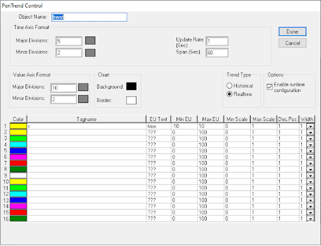
In the tab opened you can modify the update rate in seconds. For the specified time in the update rate, the data will get updated to the graph.

You can also give up to 16 tags in a single trend object. All the waveforms will be displayed in a single graph.

You can also give a minimum and maximum value of the tag that you want to display in a waveform.

The maximum value of the tag that I am using is 5 and the minimum value is 0. I have given some extra range.

Now let’s go to run time and check whether the data is acquired.
Now you can see from the above image that the data is getting updated for the time you have mentioned in the update rate.
The graph will get updated left to right the old values will get disappeared and new ones will appear in the right.

Historical Trends
As the name indicates, historic trends are used to display the data in real-time at the same time the old data can be retrieved and viewed on the run time.

Whereas in the former it is not possible.

To enable Historical logging in Intouch SCADA go to, Special –> Configure –> Historical Logging.

The dialog box in the image appears now click enable Historic logging and mention the number of days the data has to log for.
Click Ok and Now go to The tag dictionary and open the tag that we are acquiring data from.

Now enable log data in Checkbox. Click save and Ok.
Now let’s go to run time and see how to view the historical data,
On the run time click on the trends a dialog box named trend control will appear.

Now click on Historical Trends, Mention the start time and the end time for which the data you need. Click Done.

Now the historical for the mentioned time will be displayed on the run time as shown below.


Comments

Popular posts from this blog

Ferrules and Cross Ferruling

 Ferrules are identification labels provided for every wire terminations in an instrument, equipment, or electrical/instrumentation control panels. These tube-shaped sleeves can be inserted easily on each individual wire in a multi-core cable. In earlier days fixed digits/letters are used as ferrules, but now Instrumentation engineers/technicians prints out desired ferrules by using a ferrule printing machine. Typical Ferrule The numbers/ letters on the ferrules will be given as per the approved electrical hook up or loop diagrams. This helps technicians to easily identify a particular loop/wiring from a series of terminal blocks and to troubleshoot the desired terminal connection. Separate numbers on the ferrules distinguish the positive and negative polarities of wires, thus ensure the polarity protection of the instrument. Cross Ferruling  As a wire is connected on its both ends, it is quite useful to use a cross reference method for wire identification. Unlike normal ferru...

PLC Program for Mixing Tank

 Create a ladder diagram for controlling a batch mixing process. Implement a PLC program for mixing tank or Mixing Process using PLC Ladder Logic. PLC Program for Mixing Tank Fig : Mixing tank A tank is used to mix two liquids. The required control circuit operates as follows: A. When the START button is pressed, solenoids A and B energize. This permits the two liquids to begin filling the tank. B. When the tank is filled, the float switch trips. This de-energizes solenoids A and B and starts the motor used to mix the liquids together. C. The motor is permitted to run for 1 minute. After 1 minute has elapsed, the motor turns off and solenoid C energizes to drain the tank. D. When the tank is empty, the float switch de- energizes solenoid C. E. A STOP button can be used to stop the process at any point. F. If the motor becomes overloaded, the action of the entire circuit will stop. G. Once the circuit has been energized, it will continue to operate until it is manually stopped. Solution...

What is a Torbar? – Averaging Pitot Tubes

 The Torbar is employed for flow measurement of liquids, gases, or steam in circular, square, or rectangular section ducts for large flow rates. The Torbar is an insertion type multi-port self-averaging primary sensor for flow measurement. Torbar TORBAR is a set of Pitot tubes mounted on a bar across the pipeline with no moving parts. An averaging Pitot tube is a technology, while TORBAR is a manufacturing brand name. There are several brands available in the market with VERABAR, ANNUBAR, etc. Averaging Pitot Tube Principle Purpose Averaging Pitot tube can be employed when the average velocity of the flow profile, rather than the velocity in a specific point in the cross-section is desired. Averaging Pitot Tubes Principle It measures the differential pressure between the static pressure tap and the tap of full pressure of a stream. Thus such magnitude of differential pressure is directly proportional to the square of the flow rate. Working The TORBAR is designed in such a way that ...