Proximity switches Circuit Diagram Operation

 A proximity switch is one detecting the proximity (closeness) of some object. By definition, these switches are non-contact sensors, using magnetic, electric, or optical means to sense the proximity of objects.

A proximity switch will be in its “normal” status when it is distant from any detectable object.

Being non-contact in nature, proximity switches are often used instead of direct-contact limit switches for the same purpose of detecting the position of a machine part, with the advantage of never wearing out over time due to repeated physical contact.

Most proximity switches are active in design. That is, they incorporate a powered electronic circuit to sense the proximity of an object. Inductive proximity switches sense the presence of metallic objects through the use of a high-frequency magnetic field. Capacitive proximity switches sense the presence of non-metallic objects through the use of a high-frequency electric field. Optical proximity switches detect the interruption of a light beam by an object. Ultrasonic proximity switches sense the presence of dense matter by the reflection of sound waves.

Proximity Switch Symbol

The schematic diagram symbol for a proximity switch with mechanical contacts is the same as for a mechanical limit switch, except the switch symbol is enclosed by a diamond shape, indicating a powered (active) device:


Many proximity switches, though, do not provide “dry contact” outputs. Instead, their output elements are transistors configured either to source current or sink current. The terms “sourcing” and “sinking” are best understood by visualizing electric current in the direction of conventional flow rather than electron flow.

The following schematic diagrams contrast the two modes of switch operation, using red arrows to show the direction of current (conventional flow notation). In both examples, the load being driven by each proximity switch is a light-emitting diode (LED):

Principle of Operation:
Proximity Switch consists a sensor circuit and a driver circuit. The sensor circuit purpose is used to detect any near by objects. The sensor circuit sends an output High signal to the transistor based driver circuit when any object found near to the sensor circuit. The transistor based driver circuit may use NPN or PNP transistors and it depends on the application we use.

When a signal received from the sensor circuit, the transistor will be turned ON and the output will be ON. When the object is moved away from sensor circuit, the sensor output is OFF so transistor is OFF and the output will be OFF.


Note: The sensor circuit may contain a LC Resonant oscillator or a mutual induction based circuit. The LC Resonant oscillator generates a designed resonant oscillations continuously. whenever there is any metal object nearby to the sensors, the oscillations may vary and it depends on the object properties. This change in oscillations will be detected and generates an output either High or Low,  nothing but object found or not.

Proximity Switch NPN Type
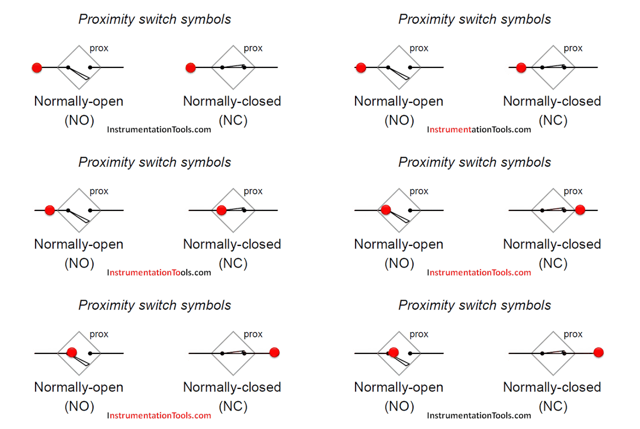
Note: The Red dot in the animation indicated the flow of current path.

Proximity Switch PNP Type
A common coloring convention for electronic proximity switches is brown for +V power supply, blue for ground (− pole of power supply), and black for the switched output signal. This convention is common to sinking and sourcing proximity switches alike.

An electronic switch designed to sink current through its signal wire is alternatively referred to as an NPN switch due to the type of transistor used in its output. Conversely, an electronic switch designed to source current through its signal wire may be referred to as a PNP switch.

The key to understanding these labels is to recognize the emitter terminal of the output transistor is always the one connected to the power supply rail. For a sinking switch, this means the emitter must connect to the negative rail, necessitating an NPN transistor to do the switching. For a sourcing switch, this means the emitter must connect to the positive rail, in which case only a PNP transistor will suffice.


Comments

Popular posts from this blog

PLC Program for Mixing Tank

 Create a ladder diagram for controlling a batch mixing process. Implement a PLC program for mixing tank or Mixing Process using PLC Ladder Logic. PLC Program for Mixing Tank Fig : Mixing tank A tank is used to mix two liquids. The required control circuit operates as follows: A. When the START button is pressed, solenoids A and B energize. This permits the two liquids to begin filling the tank. B. When the tank is filled, the float switch trips. This de-energizes solenoids A and B and starts the motor used to mix the liquids together. C. The motor is permitted to run for 1 minute. After 1 minute has elapsed, the motor turns off and solenoid C energizes to drain the tank. D. When the tank is empty, the float switch de- energizes solenoid C. E. A STOP button can be used to stop the process at any point. F. If the motor becomes overloaded, the action of the entire circuit will stop. G. Once the circuit has been energized, it will continue to operate until it is manually stopped. Solution : A

What is Relay? How it Works? Types, Applications, Testing

 We use relays for a wide range of applications such as home automation, cars and bikes (automobiles), industrial applications, DIY Projects, test and measurement equipment, and many more. But what is Relay? How a Relay Works? What are the Applications of Relays? Let us explore more about relays in this guide. What is a Relay? A Relay is a simple electromechanical switch. While we use normal switches to close or open a circuit manually, a Relay is also a switch that connects or disconnects two circuits. But instead of a manual operation, a relay uses an electrical signal to control an electromagnet, which in turn connects or disconnects another circuit. Relays can be of different types like electromechanical, solid state. Electromechanical relays are frequently used. Let us see the internal parts of this relay before knowing about it working. Although many different types of relay were present, their working is same. Every electromechanical relay consists of an consists of an Electroma

Chlorine dioxide Analyzer Principle

 Chlorine dioxide measurement Chlorine dioxide (ClO2) is an instable, non-storable, toxic gas with a characteristic scent. The molecule consists of one chlorine atom and two oxygen atoms – represented in the chemical formula ClO2. It is very reactive. To avoid the risk of spontaneous explosions of gaseous chlorine dioxide or concentrated solutions, it is generally handled in dilution with low concentrations. ClO2 is soluble in water, but tends to evaporate quickly. Typically it is prepared on site, for example from hydrochloric acid and sodium chlorite. The procedure provides solutions with approx. 2 g/l ClO2 that can be safely handled and stored for several days. Image Credits : krohne Sensor Parts : Reference electrode Applied chlorine dioxide specific potential Current needed to maintain the constant potential Counter electrode Measuring electrode The disinfection effect of ClO2 is due to the transfer of oxygen instead of chlorine, so that no chlorinated byproducts are formed. ClO2