Why Orifice Plate is having a 3:1 Turndown Ratio in Practice?
It is a general practice in the differential type flow meter, using flow orifice plate as a flow element, to limit the using in a 3:1 to 4:1 turndown ratio. Where this general practice comes from?
Orifice Plate Turndown ratio
The limitation of the DP type flow meter using orifice isn’t comes from the beta ratio limitation of the flow orifice plate nor any other flow orifice plate dimension. The limitation is comes from the error reading caused by the un-linear relationship between the differential pressure across flow orifice plate and the calculated flow rate.
In simplify concept we can calculate the orifice flow rate by:
Qm = C x (Differential Pressure)^0.5
Where,
Qm : Flow rate
C : Meter Constant
Differential Pressure : differential pressure across flow orifice plate
From the above equation we know that the flow rate is proportional to the square root of the differential pressure. This un-linear relation produces a significant error in the lower flow when the turndown ratio is exceeding 3:1.
Basically the differential pressure transmitter it self can have a turndown ratio up to 100:1 but the square root extraction limits its capability in the upper range only.
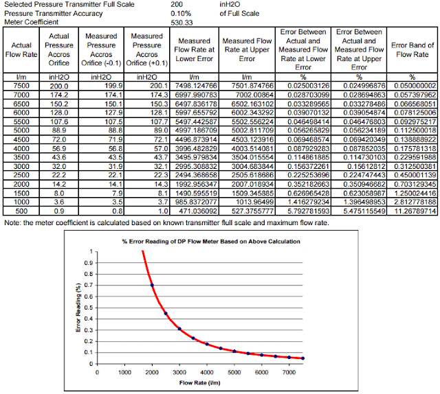
See below calculation example that illustrates the increasing of error reading when the turndown ratio is below 3:1.
Home » Orifice Plate Turndown ratio
Flow Measurement
Orifice Plate Turndown ratio
Why Orifice Plate is having a 3:1 Turndown Ratio in Practice?
It is a general practice in the differential type flow meter, using flow orifice plate as a flow element, to limit the using in a 3:1 to 4:1 turndown ratio. Where this general practice comes from?
Orifice Plate Turndown ratio
Orifice Plate Turndown ratio
The limitation of the DP type flow meter using orifice isn’t comes from the beta ratio limitation of the flow orifice plate nor any other flow orifice plate dimension. The limitation is comes from the error reading caused by the un-linear relationship between the differential pressure across flow orifice plate and the calculated flow rate.
In simplify concept we can calculate the orifice flow rate by:
Qm = C x (Differential Pressure)^0.5
Where,
Qm : Flow rate
C : Meter Constant
Differential Pressure : differential pressure across flow orifice plate
From the above equation we know that the flow rate is proportional to the square root of the differential pressure. This un-linear relation produces a significant error in the lower flow when the turndown ratio is exceeding 3:1.
Basically the differential pressure transmitter it self can have a turndown ratio up to 100:1 but the square root extraction limits its capability in the upper range only.
See below calculation example that illustrates the increasing of error reading when the turndown ratio is below 3:1.
Example of Orifice Flow Meter Error Reading Calculation
From the above example, we know that the % error reading (after perform the above square root calculation) is increasing along with the flow rate decreasing. The % error reading is exceeding 0.5% when the flow rate is lower than 2500 l/m.
Let set this flow rate as our minimum flow rate since the flow rate measurement is having high error below this point. If we look further, the 2500 l/m minimum flow and 7500 l/m maximum flow is correspond to the 3:1 turndown ratio. This is where the 3:1 turndown ratio is applied in our general practices.
If we insist to have minimum flow let say 1000 l/m then we will have a turndown ratio 7.5:1. This will lead us to get an error reading of 2.8 % which means a very bad measurement accuracy.
Thus some engineer usually simply use a 3:1 turndown ratio as their rule of thumb to decide whether they will use DP type flow orifice plate flow meter or not.
If the required turn down is higher than 3:1, then it will be better if we use another type of flow meter even though it is possible to have such higher turn down ratio by installing a parallel DP type flow orifice plate flow meter with a split range configuration.
I don’t have any reason regarding this except the parallel configuration will give us a high cost of material procurement.


Comments
Post a Comment