Presence Sensing is the act of detecting the presence or absence of an object with a contact or non-contact sensing device. The sensors then produce an electrical output signal that can be used to control equipment or processes.
Limit switches are a type of sensor that detect presence and absence. Specifically, mechanical limit switches are switches that are mechanically activated, meaning that they have some sort of arm, lever, knob, plunger, etc., which is physically—or mechanically—activated by making contact with another object. As the object makes contact with the actuator of the switch, it eventually moves the actuator to its “limit” where the contacts change state. Other varieties of sensors/switches exist, including proximity sensors, light sensors, electric switches, among others.
Mechanical limit switches are contact sensing devices widely used for detecting the presence or position of objects in industrial applications. The term limit switch is derived from the operation of the device it-self. As an object (or target) makes contact with the operator of the switch, it eventually moves the actuator to the “limit” where the electrical contacts change state.
Through this mechanical action, electrical contacts are either opened (in a normally closed circuit) or closed (in a normally open circuit). Inductive proximity, capacitive proximity, and photoelectric sensors perform this same process through noncontact sensing.
In its simplest form, a limit switch is a “switch” that can be mounted into remote locations so that it is actuated by an object other than a human operator. Some basic functions of limit switches are:
Detecting presence/absence
Counting
Detecting range of movement
Detecting positioning & travel limit
Breaking a live circuit when unsafe conditions arise
Detecting speed
…and hundreds of other applications
Mechanical limit switches can be found in any industrial or commercial application where detection or safety is needed.
Limit switches are a practical solution for sensing in most situations. There are, however, a few disadvantages to using limit switches. Some of the strengths and weaknesses are listed below:
Benefits of Limit Switches
Can be used in almost any industrial environment
Very precise in terms of accuracy and repeatability
Consume little electrical energy
Can switch loads with high inductance
Can control multiple loads
Limitations of Limit Switches
Generally restricted to equipment operating at relatively low speeds.
Must make direct contact with target.
Moving mechanical parts will wear out
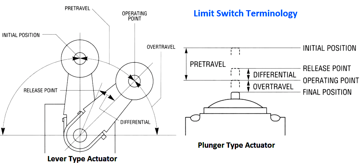
Limit Switch Terminology

Pretravel : the distance or angle that the actuator must go through to trip the contacts
Operating Point : position of the actuator at which the contacts snap to the operated position
Release Point : the position of the actuator at which the contacts return to their original state
Differential : distance (degrees) between contacts trip and contacts reset
Overtravel : movement of the actuator beyond the contacts trip point
Initial Position : position of actuator when no external force is ap-plied to the actuator
Operating force (torque) : force required to move the actuating element
Minimum return force (torque) : minimum force required to return actuator to its initial position
Total Travel : the maximum allowable distance the actuating ele-ment can travel
Repeat Accuracy : ability of a switch to repeat its characteristics precisely from one operation to the next operation
Limit Switch Functional Parts :
Most limit switches contain the following functional parts in one form or another.
Actuator/Operating Head
The actuator is the part of the switch which physically comes in contact with the target. In some limit switches, the actuator is attached to an operating head which translates a rotary, linear, or perpendicular motion to open or close the electrical contacts of the switch.
Switch Body
The component containing the electrical contact mechanism.
Receptacle/Terminals
The component containing the terminal screws or screw/clamp assembly necessary for wiring purposes. While there are a number of different styles of limit switches available in the market today, this manual will describe two classes of limit switches — standard industrial oiltight and precision switches.
Types of Limit Switches
A-Shape & E-shape:
Roller lever
Levers and roller levers actuate radially, that is they rotate on an axis. Roller levers are tipped with a roller to lessen the friction and the force required to activate the lever. Levers spring-return to neutral when the force is removed. This is one of the most popular styles of switch operators.
Adjustable roller lever
Similar to a standard roller lever, but the length of the lever is adjustable anywhere from a few millimeters to up to 5 centimeters. The rollers are also available in various diameters.
B-Shape:
Rounded plunger
Plunger heads come in many varieties and sizes. Plungers are actuated by a perpendicular force applied directly to the end of the plunger.
C-Shape:
Roller plunger
When a plunger switch is needed, but the force will not be applied directly at a 90º angle, a roller plunger can be used. The roller translates some of the nonperpendicular force into perpendicular force that can actuate the plunger.
D-Shape:
Rod lever
Rod levers are also actuated radially like levers; however these are thin rods that are much longer. Adjustable rods can be as long as 10 or more centimeters.
F-Shape:
Lateral rounded plunger
This plunger head varies from the standard B-shape in that the plunger is perpendicular to the switch.
G-Shape:
Lateral roller plunger
This plunger head varies from the standard C-shape in that the plunger is perpendicular to the switch.
Additional Operators:
Flexible rod
Similar to a rod lever in their length and appearance, rods (whiskers, spring rods, etc.). However, unlike levers that actuate only in one plane, flex rods activate in 360º
Cable pull
These switches are tipped with a lanyard to which can be attached a cable. Pulling or tightening the cable draws out the springloaded lever, which activates the switch.
Rotative Axis
These switches can be installed onto an axis (i.e., a door hinge) so that when the hinge or axis turns, the switch actuates.
Latch/Reset
Latch & reset switches can come in a variety of operating head styles. These switches do NOT spring return to neutral; instead, they latch when activated and must be physically, manually released before being deactivated.
Key Latch
This switch is coupled with a “key”. Once removed from the keyhole, the switch is actuated. Returning the key to the hole deactivates the contacts. Commonly used in door jams to shut off power when opened.
Mounting considerations
Considering which type of switch to use is important when applying a limit switch. But just as important is determining where and how to mount the switch.
Cam design
In many situations, such as a conveyor system, a cam is used to operate the actuator. The cam should be of a shape that does not allow the actuator to receive a severe impact or that releases the actuator suddenly, allowing it to snap back freely.
Mounting location
Limit switches should never be mounted in locations that could allow false operations by normal movements of operator or machine components. They should be mounted rigidly, be maintenance accessible, and have the side of the body with the cover screws facing outward.
If liquid intrusion is a possibility, the switch should be mounted face down to allow gravity to prevent seepage through the seals on the operating head. All conduit connections should be tightly sealed.
In applications where machining chips or other debris accumulates, the limit switch should be mounted in a location or at such an angle that minimized buildup on the operating head.
Applications:
Limit switches are very commonly used devices. Think about these simple applications:
What keeps the microwave from starting without the door being shut first?
What turns the light off when the refrigerator door is closed?
Why do your car’s dome lights come on when you open the door?
What stops the washing machine when a load becomes unbalanced?
Some of many industries with limit switch needs:
Material handling – packaging, moving, warehousing, distribution
Food & beverage packaging, distribution
Manufacturing – automotive/heavy equipment, machining, marine/aviation, glass & plastics
Metals – mining, refining, processing, forming
Commercial applications
Control cabinets
Many, many more!


Comments
Post a Comment