Fiber Optic Cable
Fiber optic cable transmit information as light pulses, rather than the electrical impulses used by traditional wire cables. They may be used to convey voice, video and data.
The fiber optic cables have a glass core covered with cladding, coatings, and, typically, Kevlar membranes to add strength. Finally, a protective outer coating seals the cables from the elements.
The cables may be connected to communications equipment and patch panels, providing any necessary physical connection.
Operating Principle
It is the optical fibers in the fiber optic cables that carry the light, and allow information to be transmitted. These consists of a core and a cladding layer, selected for total internal reflection due to the difference in the refractive index between the two.

Individual coated fibers (or fibers formed into ribbons or bundles) then have a tough resin buffer layer and/or core tube(s) extruded around them to form the cable core. Protective sheathing is added for protection, depending on the application.
To prevent “cross-talk” between the fibers, sometimes they are encased in dark, light absorbing materials. This prevents the light from one fiber from leaking through to another. Several layers of protective sheathing, depending on the application, are added to form the cable.
Types
The three types of fiber glass are shown here
Connectors
Commonly used connectors are shown in the table below.

Joining Fiber Optic Cables
There are two methods of fiber optic splicing, fusion splicing & mechanical splicing. Splices are “permanent” connections between two fibers. Typically, the reason for choosing one method over the other is economics. Fusion splicing is lower per connection; however, the initial investment is much higher.
Mechanical splices are simply alignment devices, designed to hold the two fiber ends in a precisely aligned position thus enabling light to pass from one fiber into the other. (Typical loss: 0.3 dB). Mechanical splicing has a low initial investment, but costs more per splice.
When joining optical fibers, it is critical for the opposed cores to be properly aligned. The primary specification for connectors or splices is loss or the amount of light lost in the connection. Improper alignment where the optical fibers are not perfectly aligned will result in part of the light to be loss through the bad junction.
There are four main causes of optical loss mostly caused by:
1. Poor core alignment:
Poor alignment of joined optical fiber cores causes a connector/splice optical loss.
2. Axial run-out:
A connector/splice optical loss occurs due to an axial run-out (improper cut angles) between the optical fibers to be joined.
It is necessary to avoid an increased angle at fiber cut end when using an optical fiber cleaver (cutting device) before fusion splicing, since such an angle can result in splicing of optical fibers with run-out.
3. Gap:
An end gap between optical fibers results in a connector/splice optical loss.
For example, if optical fiber end faces are not correctly butt-joined in mechanical splicing, a splice loss results due to the refraction of the light in the air gap between fibers.
An end gap between optical fibers results in 0.6 dB of return loss at the maximum due to the change in refractive index from the optical fiber to the air.

4. Reflection:
The end of the fiber must be properly polished and clean to minimize loss. A rough surface will scatter light and dirt can scatter and absorb light. Since the optical fiber is so small, typical airborne dirt can be a major source of loss.
Cleaning optical fiber ends is important for optical connectors.
In addition, the whole optical connector ends should be cleaned because loss can also occur due to dirt between optical connector ends.
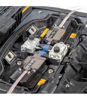
Fusion Splicing
Fusion splicing involves joining two optical fibers end-to-end using some source of heat.
The end result is fusing the two fibers together so that light passing through the fibers is not scattered or reflected back by the splice, and so that the splice and the region surrounding it are almost as strong as the virgin fiber itself.
This produces a continuous connection between the fibers enabling very low loss light transmission. The source of heat is usually an electric arc, but can also be a laser, or a gas flame, or a tungsten filament through which current is passed.
Fusion splicing is the most widely used method of splicing as it provides for the lowest loss and least reflectance, as well as providing the strongest and most reliable joint between two fibers.


Comments
Post a Comment